
Page last updated 30/08/2018

Concrete dome biogas plant (Janata) design
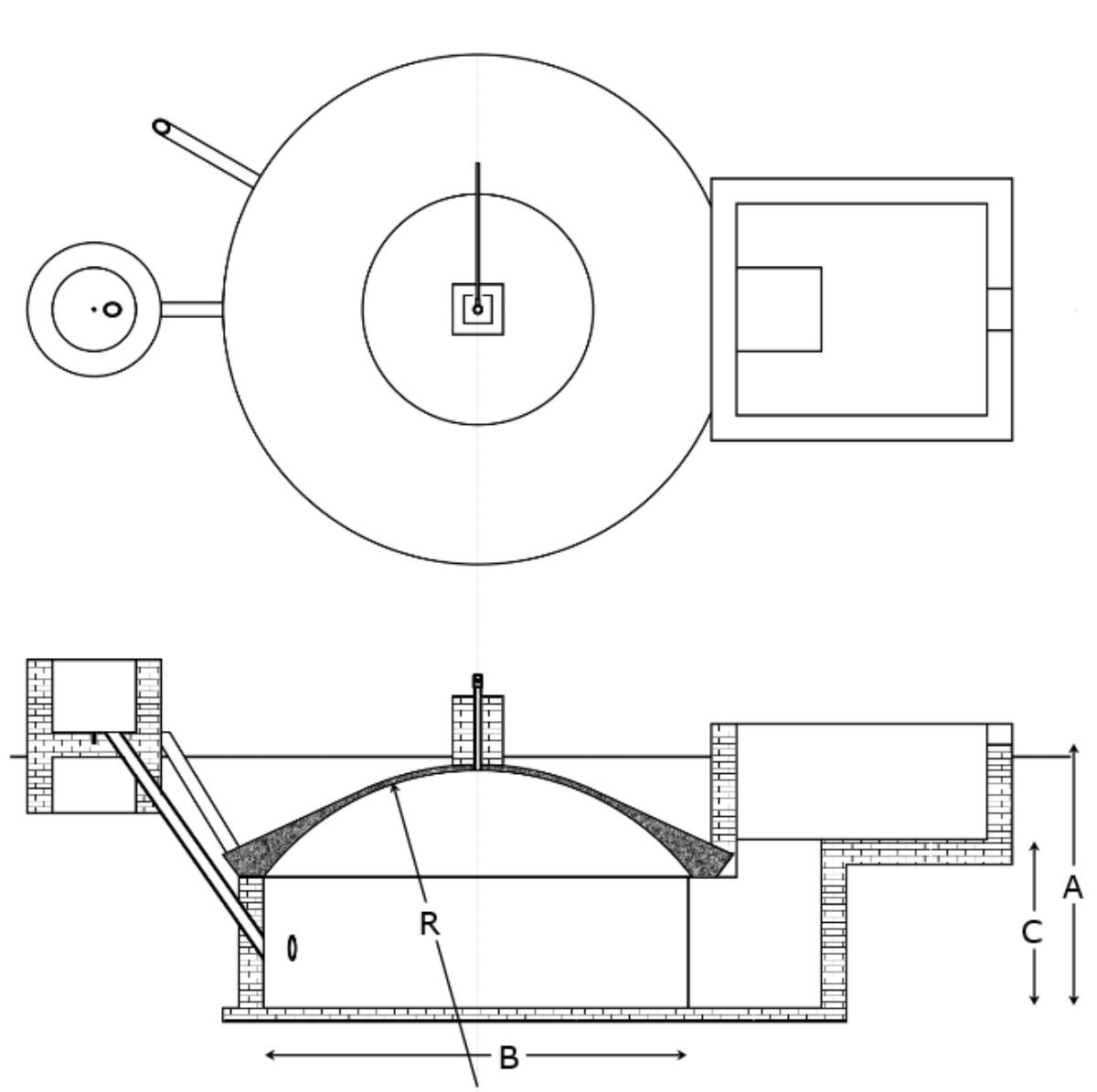
Parameters for concrete dome design

Parameter

Length (m)

A

1.62

B

2.04
C
0.86
R
1.13
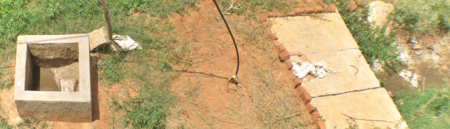
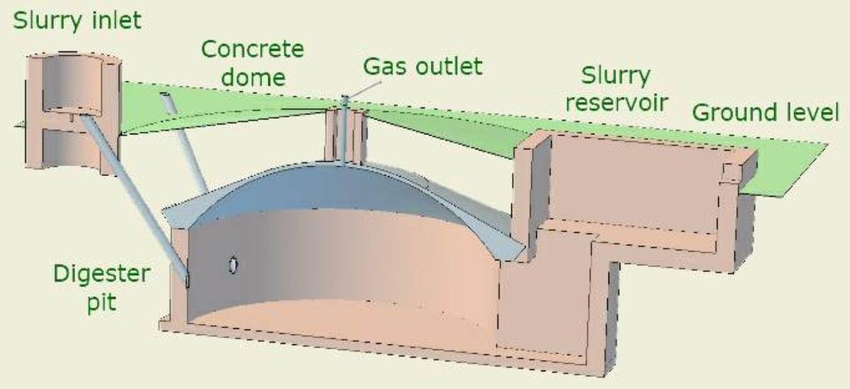
Drawing of a concrete dome plant
Diagram of a concrete dome plant used in Nepal
The GGC 2047 biogas plant was first developed by DCS and improved and used by GGC for the extension work under UNDP. A
standardised design was used, to allow for quality control. The plant is built by digging a hole, placing a floor and then building a
cylindrical wall, with one or more slurry feed pipes and a slurry outlet put in place. The hole is refilled with soil and the top is
shaped with a template, that acts as a mould for the concrete dome. Once the concrete has set, the soil is dug out and the inlet
and reservoir tanks built with bricks. The dome is then backfilled with earth to place it under compression.
A standard GGC 2047 plant has a calculated total internal volume of 6 m
3
, although not all of the internal volume is used for slurry.
The design is very strong and a survey of installed plants showed that 95% survived an earthquake in Nepal, although many of the
gas lines broke.
The equations for a volume of a section of a sphere can be used to calculate the volume of the dome while the cylindrical section is
given by the relevant equation.
There are a range of different sizes for GGC 2047 concrete dome plants, including much larger ones.
More details of biogas plant designs are given in the book.


Page last updated 30/08/2018

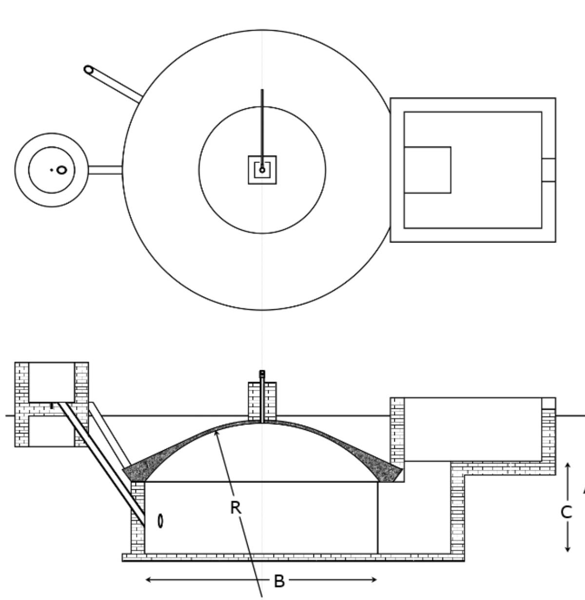
Diagram of a concrete
dome plant used in Nepal
The GGC 2047 biogas plant was first developed by DCS and
improved and used by GGC for the extension work under
UNDP. A standardised design was used, to allow for quality
control. The plant is built by digging a hole, placing a floor and
then building a cylindrical wall, with one or more slurry feed
pipes and a slurry outlet put in place. The hole is refilled with
soil and the top is shaped with a template, that acts as a
mould for the concrete dome. Once the concrete has set, the
soil is dug out and the inlet and reservoir tanks built with
bricks. The dome is then backfilled with earth to place it under
compression.
A standard GGC 2047 plant has a calculated total internal
volume of 6 m
3
, although not all of the internal volume is used
for slurry. The design is very strong and a survey of installed
plants showed that 95% survived an earthquake in Nepal,
although many of the gas lines broke.
The equations for a volume of a section of a sphere can be
used to calculate the volume of the dome while the cylindrical
section is given by the relevant equation.
Parameters for concrete dome
design

Parameter

Length (m)

A

1.62

B

2.04
C
0.86
R
1.13
Drawing of a concrete
dome plant used in Nepal


